A navigation lock is a valve between two water bodies that should never mix. Every time it cycles, a chamber of one is handed to the other. At the Hiram M. Chittenden (Ballard) Locks, that means seawater from Puget Sound moving into the Lake Washington Ship Canal, the migration corridor for Chinook and steelhead fish.
How you represent that handoff in a model decides two things: what the model can show, and how much work it takes to get there.
Two ways to model a lockage
Specified flow treats the fill and drain as bookkeeping. You prescribe a volume and a schedule, and a withdrawal/return pair moves that water from point A to B. It is exact and stable, but if a lift estimate is off, the chamber opens with a head across the gate.
Dynamic exchange keeps the same gates but computes the fill and drain. Each time step, a level-balancing controller sets the withdrawal/return flow so the chamber matches the next pool by the time the gate is scheduled to open. The volume of each fill or drain is a result, set by the chamber area and the actual pool levels; you supply only the gate schedule and a fill time.
In both modes, once a gate opens, the exchange through it is computed by the hydrodynamics: dense water slides in along the bed while fresher water leaves at the surface. In the following figure a saline bay is shown on the left and a freshwater lake on the right, and the chamber cycles between the two levels.
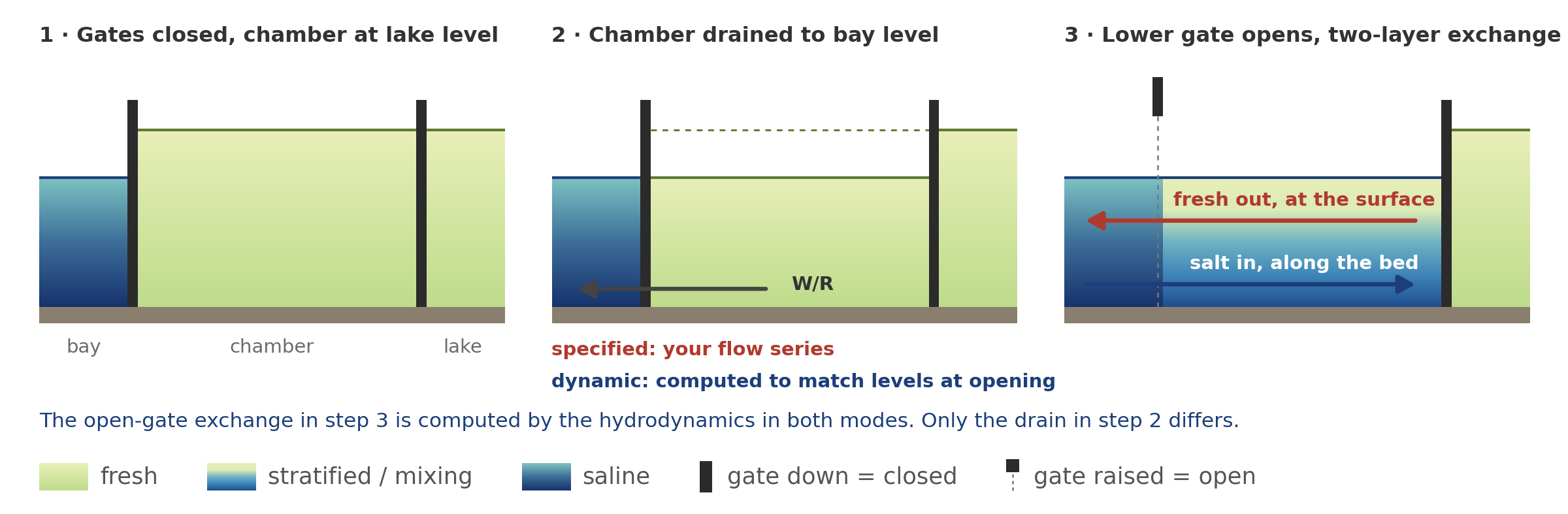
Figure 1. One downbound lockage. Only the drain in step 2 differs between the two modes.
What each setup asks of you
In EE, both approaches start with the same lock. Each gate is represented as a Navigation Lock hydraulic structure on the cell faces where it is located and is opened and closed according to a gate time series derived from the lockage log. The difference lies in how the chamber is filled or drained while the gates are closed.
| Aspect | Specified flow | Dynamic exchange |
|---|---|---|
| Lockage log | Build a gate time series, then calculate the transfer volume and flow rate for each lockage. | Build the gate time series only; the model determines the resulting water exchange. |
| Chamber water levels | Computed by the model from the prescribed flows, but the lift behind each volume is estimated by the user from tide and lake-level data. | Brought to the level of the next pool before each opening. |
| Volume and duration per lockage | Calculated and entered for each lockage. | Volume emerges from chamber geometry and computed head; fill/drain time is set once per gate. |
| What you define in EE | Navigation Lock gates with their time series, plus a W/R group and flow time series for each water transfer. | Navigation Lock gates with Use Dynamic Flows enabled, a fill/drain time, and a linked filling/emptying W/R group with no prescribed flow series. |
| Multiple chambers | Each transfer is a separate W/R group and flow series, kept consistent manually. | Each gate is linked to its filling/emptying W/R group, so chamber transfers follow gate operations automatically. For chambers in series, each gate’s time-control reference cell is linked to the gate immediately upstream. |
Specified flow: build the flows yourself.
The gate series says when water moved, not how much. So, before anything goes into EE:
- Estimate the lift for every lockage from the tide and lake level at that moment.
- Turn the lift into a volume using the chamber area, then into a flow rate over an assumed fill or drain duration.
- Build a flow time series for each fill and drain, in every chamber, set to zero whenever a gate on that side is open.
- Set up a W/R group for each series, with its withdrawal and return cells.
Dynamic exchange: tick a box, pick a group.
Same gate dialog, same gate series. Switching it on changes three fields:
- Use Dynamic Flows: checked
- Time to Fill/Drain the Lock: how long filling or emptying takes
- Withdrawal/Return Group for Filling/Emptying: the group that moves water into or out of the chamber. Its time control follows the lock’s opening and closing, so it needs no flow series.
No volumes or flow rates are entered anywhere.
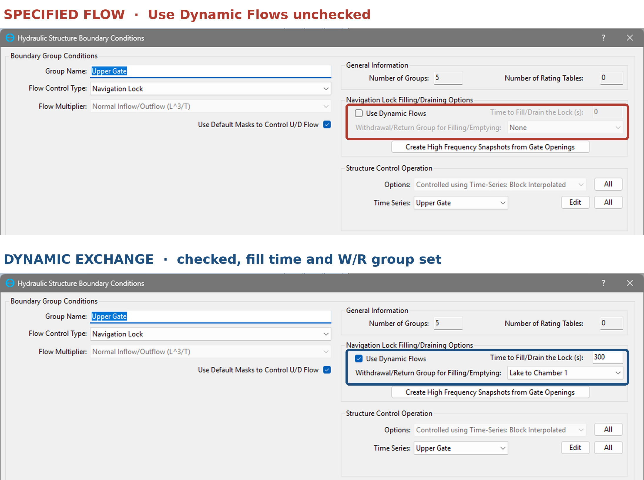
Figure 2. The same gate configuration tab under each approach.
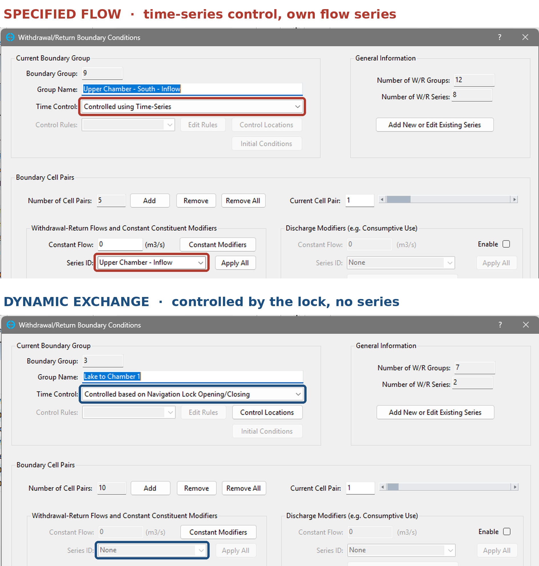
Figure 3. The same W/R configuration tab under each approach.
Example Model: Ballard Locks
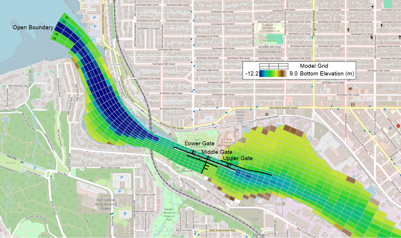
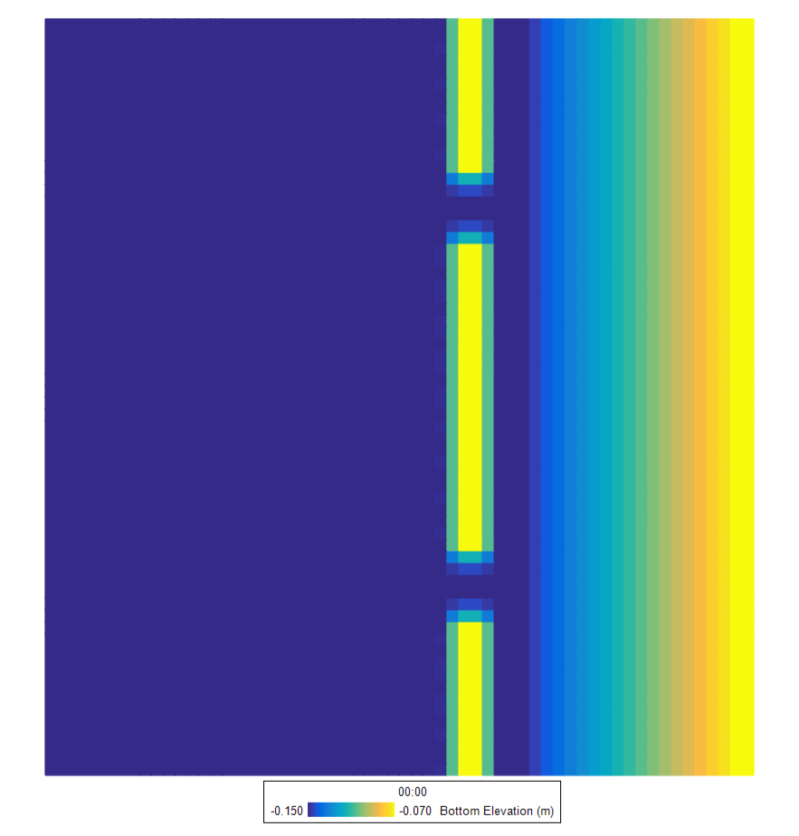
Figure 4. Model grid and bottom elevation, from the open boundary in Shilshole Bay, through the locks, to the lake side of the Ship Canal.
A multi-layer grid resolving the full Ship Canal from Shilshole Bay to Lake Washington. The large lock is represented as two chambers in series, with the small lock alongside, plus the spillway and fish ladder.
Over a run of several months, the lockage record holds hundreds of events for each chamber. Under specified flow, every one of them becomes a row in a flow series that someone has to derive before the model can start. Under dynamic exchange, the gate time series already in the model was enough.
The snapshots below come from the dynamic run. Saltier water from the bay fills the downstream canal and reaches into the lower chamber, while the lake side of the upper gate stays fresh. Temperature follows the same boundary. None of this exchange was prescribed: it comes from the gates opening and closing on their time series, with the model working out the flows.
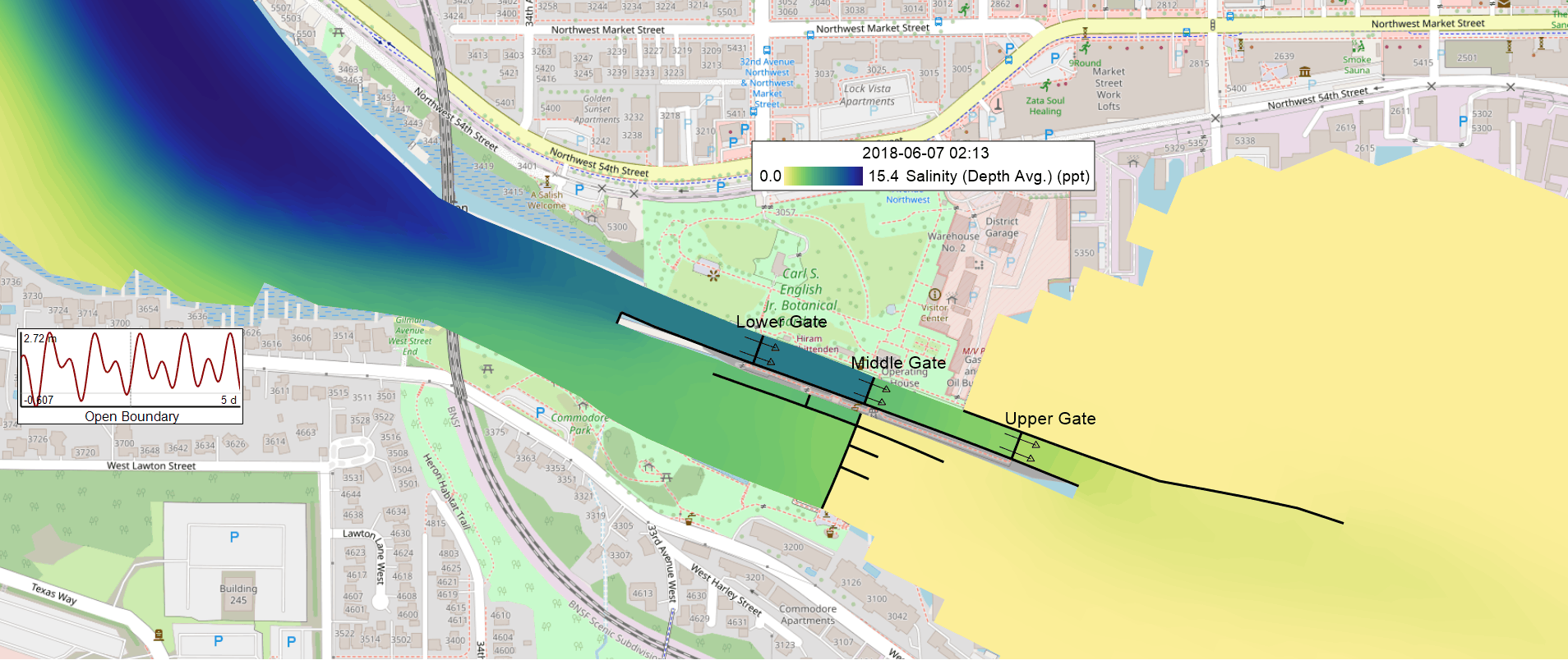
Figure 5. Depth-averaged salinity around the locks under dynamic exchange.
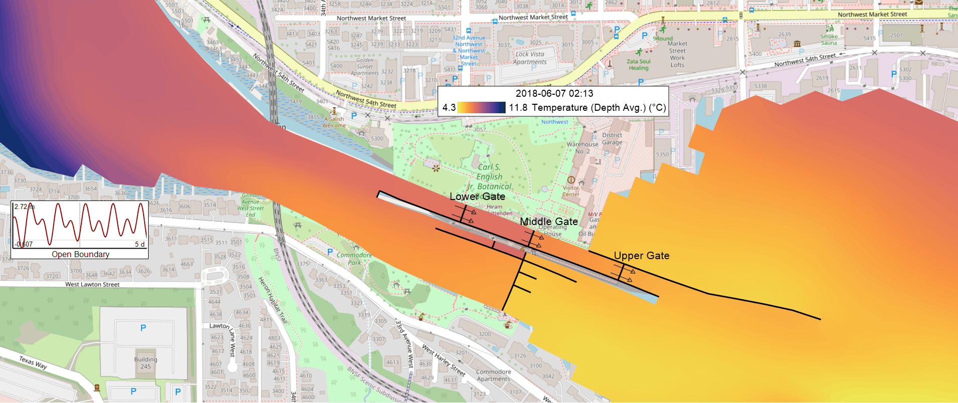
Figure 6. Depth-averaged temperature at the same time step.
A vertical slice along the locks is shown in the following animation, the exchange plays out the way Figure 1 sketches it. Each time a gate opens, salty water slides into the chamber along the bed while fresher water spreads out over the top. Some of that salt carries on past the lake-side gate and settles into the deeper channel beyond it.
Conclusion
Specified-flow option can be applied for short runs with a known, measured lockage volume record; reproducing an existing study. Dynamic-flow option is appropriate for long runs, scenarios (sea-level rise, changed schedules), and multi-chamber locks.
The simpler setup also allows the lock to behave as a lock should, with chamber levels following the actual pool levels instead of hand-estimated lifts. By minimizing manually prescribed inputs, it also reduces the potential for user-induced errors.